
Not counted towards your tag license limit.
The CIP (Control and Information Protocol) driver type provides an interface between VTScada and hardware that uses the CIP or ENIP standards or both for communications.
It has been reported that response time from the CIP driver has been improved by increasing the system overhead time slice setting within the PLC from 20% to 70% using Logix 5000 or Studio 5000 software.
Use this information with caution, taking your unique situation into account. It may be less relevant for newer systems.
Driver Errors: To learn more about the cause of an error condition, refer to the Driver Summary Report and the Driver Error Report, both of which are available in the Reports page. The Show Stats button will also provide current and last error messages: Show Statistics Button Widget
The CIP driver is able to query the PLC and import (create) tags in your application automatically. Before attempting the import, ensure that:
- You are connected to an Allen Bradley CIP device.
- Your application is not pending a restart.
- Your account has the Tag Modify privilege
Instructions and error descriptions are provided in Import Tags from PLCs.
When this driver is used in combination with a TCP/IP tag, the standard TCP port is 44818
Notes About Allen Bradley ControlLogix Tags
The ControlLogix family of PLCs use tag names to identify data objects in the PLC. The type of data object must be specified when writing to a particular tag. The ControlLogix family of PLCs supports the following atomic types:
- Boolean (BOOL)
- 8-bit Signed Integer (SINT)
- 8-bit Unsigned Integer (BYTE)
- 16-bit Signed Integer (INT)
- 32-bit Signed Integer (DINT)
- 32-bit Unsigned Integer (DWORD)
- 32-bit Float (REAL)
In addition, 2-dimensional arrays are supported, thus an array of any type listed above is possible:
- DINT[32] - a 32-element array of DINTs.
The ControlLogix family of PLCs also supports a structure. A structure is a collection of the following atomic types. For example, a Timer has the following fields:
- Timer.PRE - DINT
- Timer.ACC - DINT
- Timer.EN - BOOL
- Timer.TT - BOOL
- Timer.DN - BOOL
- Timer.FS - BOOL
- Timer.LS - BOOL
- Timer.OV - BOOL
- Timer.ER - BOOL
The VTScada driver can read and write to all of the atomic data types within the structure. The VTScada driver can also read a stream representation of a structure. It does not have any knowledge of the contents of the structure. At present, the driver cannot write an entire source.
It should be noted that even the atomic data types are themselves structures (of a special sort that can be read and written). For example, an INT is actually an array of 16 BOOLS, 1 representing each bit in the INT. It is possible to read and write a bit of an INT by addressing it correctly (i.e. INT_TAG1|INT will write to the least significant bit of INT_TAG.).
This driver has the ability to save the last value written to each output tag, and to rewrite those values, either automatically when lost communications are restored, or manually by the press of a button. Carefully review the information in the Connection tab to decide whether this feature should be used in your application.
If this driver is being used in conjunction with a Driver Multiplexer, then configure the Driver Multiplexer to store the last values, not the drivers connected to the Multiplexer. In this case, only the Multiplexer should be configured to re-write automatically.
The ID tab of every tag includes the same common elements: Name, Area, Description, and Help ID.
Name:
Uniquely identifies each tag in the application. If the tag is a child of another, the parent names will be displayed in a separate area before the name field.
You may right-click on the tag's name to add or remove a conditional start expression.
Area
The area field is used to group similar tags together. By defining an area, you make it possible to:
- Filter for particular tag groups when searching in the tag browser
- Link dial-out alarm rosters to Alarm tags having a particular area
- Limit the number of tags loaded upon startup.
- Filter the alarm display to show only certain areas.
- Filter tag selection by area when building reports
When working with Parent-Child tag structures, the area property of all child tags will automatically match the configured area of a parent. Naturally, you can change any tag's area as required. In the case of a child tag, the field background will turn orange to indicate that you have applied an override.
To use the area field effectively, you might consider setting the same Area for each I/O driver and its related I/O tags to group all the tags representing the equipment processes installed at each I/O device. You might also consider naming the Area property for the physical location of the tag (i.e. a station or name of a landmark near the location of the I/O device). For serial port or Roster tags, you might configure the Area property according to the purpose of each tag, such as System or Communications.
You may define as many areas as you wish and you may leave the area blank for some tags (note that for Modem tags that are to be used with the Alarm Notification System, it is actually required that the area field be left blank).
To define a new area, type the name in the field. It will immediately be added. To use an existing area, use the drop-down list feature. Re-typing an existing area name is not recommended since a typo or misspelling will result in a second area being created.
There is no tool to remove an area name from VTScada since such a tool is unnecessary. An area definition will exist as long as any tag uses it and will stop existing when no tag uses it (following the next re-start).
Description
Tag names tend to be brief. The description field provides a way to give each tag a human-friendly note describing its purpose. While not mandatory, the description is highly recommended.
Tag descriptions are displayed in the tag browser, in the list of tags to be selected for a report and also on-screen when the operator holds the pointer over the tag’s widget. For installations that use the Alarm Notification System, the description will be spoken when identifying the tag that caused the alarm.
The description field will store up to 65,500 characters, but this will exceed the practical limits of what can be displayed on-screen.
This note is relevant only to those with a multilingual user interface:
When editing any textual parameter (description, area, engineering units...) always work in the phrase editor. Any changes made directly to the textual parameter will result in a new phrase being created rather than the existing phrase being changed.
In a unilingual application this makes no difference, but in a multilingual application it is regarded as poor practice.
Help Search Key
Used only by those who have created their own CHM-format context sensitive help files to accompany their application.
Server List
Select (or create) a named server list.
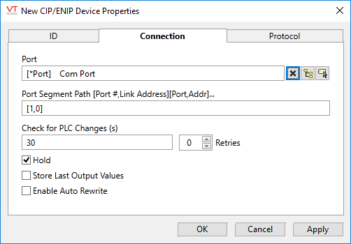
CIP Driver properties Connection tab
The Connection tab for a CIP driver enables you to configure the port through which communications with the hardware will take place.
Note: The TCP/IP Port Tag should be usually be configured to communicate with the PLC on port 44818 (0xAF12). You should confirm this against your PLC’s configuration.
Port
Select the TCP/IP tag that will provide the address and port to be used when communicating with the PLC.
Port Segment Path [Port #, Link Address][Port,Addr]…
The Port Segment Path format is [Port ID, Link Address], and describes the path to access the data.
The Port ID is a number that describes the port by which the message will exit the communications card that received it.
Port ID 0 is defined as the Data Highway Plus port for a KT card
Port ID 1 is the backplane from a communications card
Port ID 2 and 3 are the communication port of the communications cards.
For example port 2 on a DHRIO type card is DH+ channel A while port 3 is channel B.
The Link Address is the destination address of the message for this pair of the port segment path. You may provide an IP address for Ethernet network, slot number for a backplane, node number for DH+ and ControlNet networks and station address for DF1 networks.
For example when accessing the CPU with a built-in Ethernet port, the Port ID would be 1 for the backplane and the link address would be the slot number of the CPU. If the CPU is in slot number 0 the Port Segment Path parameter should be set to [1,0].
In newer CIP devices such as the 1756-L83E processor, use [] rather than [1,0].
Further examples:
[1,5]
The message destination is slot number 5 of the backplane.
[1,5][2,18]
The message will be directed to slot number 5 on the backplane and then out port 2 of the communications card to node or station address 18, depending on the type of network
[1,5][2,10.158.2.20][1,0]
The message will be directed to slot number 5 on the backplane, then out port 2 of the Ethernet card to IP address 10.158.2.20 and then to slot number 0 of that backplane.
You must be familiar with the hardware to which you are connecting to correctly establish the Port Segment Path.
Check for PLC Changes (s)
The CIP driver reads the entire PLC tag configuration into memory before initiating any reads, allowing it to poll data by an index instead by PLC tag name. This results in considerably faster performance. The full read of the PLC tags names does take time, but is done only once and stored.
It is necessary to scan the PLC periodically to see if anything has changed. This is a single transaction that indicates whether another full read is required. The default of 30 seconds is recommended for most installations, but may be extended if you are confident that the PLC configuration is not changing.
Operators may force a read at any time by using the "Read PLC Tags" button on the CIP Driver Command dialog.
Hold
Check this to have I/O tags attached to the driver hold their last value in the event of a communication failure. If not checked, tags will have their value set to invalid on a communication failure.
Retries
The number of times to retry a message before declaring an error.
Use only if the driver is connected to a Serial port. When using TCP/IP, do not set to any value other than 0.
Store Last Output Values
When selected, the driver will maintain a record of the last value written to each output address. This may be useful in at least two situations:
- For hardware that does not maintain its state during a power loss and must be restored to that state when re-started.
- When failed hardware is replaced by a new device and you would like to start that device with the values last written to the old one.
If the last output values are stored, they may be re-written by either of two methods:
- Automatically, when communication is restored to the device.
- Manually by way of a button press. See, Rewrite Outputs Widget for details.
Changing this value from selected to deselected will cause all stored values to be erased immediately.
If this driver is being used in conjunction with a Driver Multiplexer, then configure the Driver Multiplexer to store the last values, not the drivers connected to the Multiplexer. In this case, only the Multiplexer should be configured to re-write automatically.
Enable Auto Rewrite
If selected, the Store Last Output Values option will also be activated. This option causes the driver to rewrite the last value written to each output, in the event that communications are lost and then restored.
Use this option only if you are certain that you want the last values to be rewritten automatically after an interruption in driver communications.
CIP Driver properties Protocol tab
The Protocol tab for a CIP driver enables you to configure settings related to operation timeouts.
The properties are part of the communications protocol. You must be familiar with the CIP protocols to properly configure them. If the default values for these properties are enabling communications, don't change them.
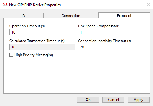
Operation Timeout
Use to specify the time (in seconds) after which the target will abort a request. The default value for Operation Timeout property is 10 (seconds).
Link Speed Compensator
VTScada has a timeout check that is similar to the Operational Timeout and matches the default value of that parameter. In a slow link environment, it may be necessary to make the VTScada timeout slightly longer to account for the transmission time on the slow link. The VTScada timeout will be the Operational Timeout parameter multiplied by the Link Speed Compensator.
Calculated Transaction Timeout(s)
This is the VTScada timeout value, calculated by multiplying the PLC's Operational Timeout by the Link Speed Compensator.
Connection Inactivity Timeout (s)
The maximum network link inactivity time in seconds. If there is no communication between VTScada and the PLC for this duration, VTScada will close the connection to the PLC. This setting can be used to terminate connections to PLC that are polled infrequently to reduce network traffic.
The connection is automatically re-established by the driver when the PLC polling is resumed. Note that the PLC's tag configuration must be re-read when the connection is re-established, therefore you must balance the cost of this increased traffic against the savings of closing the connection.
High Priority Message Flag
If the High Priority Message Flag check box is selected, the priority of messages is high and should take precedence over all else. Otherwise, the priority of messages will be normal.
The following widgets are available to display information about your application’s CIP Driver tags:
