
Not counted towards your tag license limit.
The BACnet driver follows the American Society of Heating, Refrigerating and Air Conditioning Engineers (ASHRAE) standard protocol document ANSI/ASHRAE Standard 135-2012 (Supersedes ANSI/ASHRAE Standard 135-2010) entitled, "BACnet - A Data Communication Protocol for Building Automation and Control Networks".
This driver supports Driver Discovery.
The driver was written using this standard as a protocol reference and supports protocol version 1.14. The protocol follows the seven-layer, Open Systems Interconnection (OSI) Basic Reference Model, in which each layer communicates with the immediately adjacent layer or layers.
It supports physical connections to devices that support the BACnet Virtual Link Layer over User Datagram Protocol/Internet Protocol, more commonly known as BVLL over UDP/IP or BACnet/IP.
The seven-layer OSI model:
|
Application Layer |
|
| Presentation Layer | |
| Session Layer | |
| Transport Layer | |
| Network Layer | |
| Data Link Layer | |
| Physical Layer |
Not all of these layers are required for the BACnet protocol implementation, therefore the layer diagram can be condensed as follows:
| BACnet Layers | Equivalent OSI Layers | ||||||
|---|---|---|---|---|---|---|---|
| BACnet Application Layer | Application Layer | ||||||
| BACnet Network Layer | Network Layer | ||||||
| ISO 8802-2 (IEEE 802.2) Type 1 |
MS/TP | PTP | LonTalk | BVLL | BZLL | Data Link Layer | |
| ISO 8802-3 (IEEE 802.3) |
ARCNET | EIA-485 | EIA-232 | LonTalk | UDP/IP | ZigBee | Physical Layer |
The current design model of PC software and hardware prevents a reliable implementation of physical connections to other popular networks supported by the BACnet Standard, namely MS/TP. This is because the timing requirements can easily exceed the microsecond range, which may be too fast for the task-switching mechanism of modern operating systems. Moreover, systems with many drivers running in parallel can fail to achieve the minimum timing requirements for any baud rate. Using a remote port server through an IP link considerably worsens the situation, as it adds a lag between the generation of the network layer messages and the actual transmission to the media. It may also fragment packets in a way that exceeds the framing demands of the protocol.
Therefore, communications with devices not supporting BACnet/IP are only available through routing. BACnet supports a routing system alternative to the one used by higher-layer protocols (such as UDP/IP). It is based on the use of specially designed devices called BACnet routers. They are intended to interconnect two or more BACnet networks to form a BACnet internetwork. Different networks can use different data links and technologies if they are supported by both the BACnet standard and the router network being used.
To enable routing, select the option, "Use a BACnet router", on the Device tab of the driver's configuration dialog. The UDP/IP port selected in the Communications tab will be used to reach the Ethernet port of the router. This will result in the address of the port tag being displayed in the Router IP Address field, whereas the Device IP Address will become available for the user to enter the MAC address of the target device, according to the format selected in the Device Network Type drop-list. The Device Network Number field will also become available to enter the number of the network where the device is located. VTScada will add the routing information to the header of the message, so the router can relay it to the correct destination.
A typical network structure:
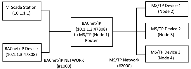
All numbers shown here are examples and may not work with your configuration. Refer to your device documentation rather than copying these.
While many other combinations are possible, this shows the typical scenario for a VTScada application. More information may be obtained at http://www.bacnet.org.
Because PC software and hardware evolved in a way that favors the concentration of all communications in a single IP-based link, using a BACnet router to manage low-level serial communications with compatible devices provides a much simpler and more reliable configuration. From VTScada’s perspective, all devices will be seen as BACnet/IP devices, even though routed devices will share a single UDP/IP port and address, and still rely on a typically slower media.
To use the configuration shown on the diagram, four BACnet drivers are required, configured as follows:
Numbers shown in the following tables are examples.
Refer to the hardware documentation for your device rather than copying these values.
| BACnet/IP Device | MS/TP Device 1 | MS/TP Device 2 | MS/TP Device 3 | |
| Port | UDP Port 1 | UDP Port 2 | UDP Port 2 | UDP Port 2 |
| Device IP/Node | (Set by Port) | 2 | 3 | 4 |
| Network Type | - | MS/TP | MS/TP | MS/TP |
| Device Network # | - | 2000 | 2000 | 2000 |
| Router IP | - | (Set by Port) | (Set by Port) | (Set by Port) |
| Use a BACnet router | - | Enabled | Enabled | Enabled |
The two ports would be set with the following:
| UDP Port 1 | UDP Port 2 | |
| UDP/IP Name/Address | 10.1.1.3 | 10.1.1.2 |
| Remote Port # | 47808 (device-specific) | 47808 (device-specific) |
| Local Port # | 47808 | 47808 |
The local port numbers above are only an example. The standard BACnet port is 47808, but devices are required to support other ports as well. The MS/TP network node used by the router (1) is of no concern to this example, assuming that it doesn’t conflict with any other device located in the same network.
The BACnet router being used to connect to another network does not need to be directly connected to the destination network or support the destination protocol, as long as it has a path to another router that provides a connection. Each router in the link will receive the message and attempt to discover the best path to the requested network. This will continue until either the device is reached, or there are no remaining network hops available. Likewise, the response message (either successful or failed) will make its way back to the VTScada Station. Therefore, it is important that the Request and Segment timeouts are configured properly to allow enough time for the entire procedure.
Limitations
The driver currently supports basic I/O reading and writing of primitive types, including arrays of primitive items. More functionality is intended to be added throughout the next releases. Here is a list of current limitations and possible future enhancements:
- Message security is not supported within the BACnet context.
- All standard BACnet objects and their properties defined in version 1.14 are supported, although not all of them will return values that can be used by VTScada’s standard I/O tags. Some complex types, including Sequence (and therefore, sub-properties), Choice and BACnet List are not supported in this version. Arrays of primitive items can be both read and written in an item-by-item basis. Vendor-specific objects and properties are supported only if their encoding is not context-tagged.
- While some properties may be writable per the BACnet Standard, or even some intended to be read-only could be written to on specific devices, the driver only supports writing to primitive types. As this is not enforced at the driver level, they might be configured to write, but the actual communications may fail depending on the device implementation.
- The BACnet standard offers a few approaches to automatic network / device / object discovery, but this is currently not supported. Some properties or objects shown on the Address Assist dialog may not be present in the device being accessed.
- The driver does not reply to queries regarding its capabilities as it does not expose the standard "Device" object.
- Due to the limited object and property support, schedules and calendars may not be fully supported.
- Services other than ReadProperty, ReadPropertyMultiple and WriteProperty are not supported.
The following property settings hold additional configuration parameters for your BACnet driver:
BACnetAddressLimit - The upper limit for BACnet object instance numbers (default = 4194303).
BACnetDefAcronyms – When set to 1 (True), the Address Assist module will generate address strings with acronyms instead of the full-name address (default = 0).
BACnetNPDUTimeout – Timeout for the receiver to wait for the reception of a full NPDU before discarding an incomplete message (default = 10 s).
BACnetDeviceInfoRetry – Retry interval when unable to get information about the capabilities of a device (default = 30 s).
BACnetPropWinSize – Default value for the parameter proposed-window-size, which determines how many message segments, up to the maximum of 127, VTScada will accept before requiring an acknowledgement (default = 127).
The ID tab of every tag includes the same common elements: Name, Area, Description, and Help ID.
Name:
Uniquely identifies each tag in the application. If the tag is a child of another, the parent names will be displayed in a separate area before the name field.
You may right-click on the tag's name to add or remove a conditional start expression.
Area
The area field is used to group similar tags together. By defining an area, you make it possible to:
- Filter for particular tag groups when searching in the tag browser.
- Link dial-out alarm rosters to Alarm tags having a particular area.
- Limit the number of tags loaded upon startup.
- Filter the alarm display to show only certain areas.
- Filter tag selection by area when building reports.
When working with Parent-Child tag structures, the area property of all child tags will automatically match the configured area of a parent. Naturally, you can change any tag's area as required. In the case of a child tag, the field background will turn yellow to indicate that you have applied an override. (Orange in the case of user-defined types. Refer to Configuration Field Colors).
To use the area field effectively, you might consider setting the same Area for each I/O driver and its related I/O tags to group all the tags representing the equipment processes installed at each I/O device. You might also consider naming the Area property for the physical location of the tag (i.e. a station or name of a landmark near the location of the I/O device). For serial port or Roster tags, you might configure the Area property according to the purpose of each tag, such as System or Communications.
You may define as many areas as you wish and you may leave the area blank for some tags (note that for Modem tags that are to be used with the Alarm Notification System, it is actually required that the area field be left blank).
To define a new area, type the name in the field. It will immediately be added. To use an existing area, use the drop-down list feature. Re-typing an existing area name is not recommended since a typo or misspelling will result in a second area being created.
There is no tool to remove an area name from VTScada since such a tool is unnecessary. An area definition will exist as long as any tag uses it and will stop existing when no tag uses it (following the next re-start).
Description
Tag names tend to be brief. The description field provides a way to give each tag a human-friendly note describing its purpose. While not mandatory, the description is highly recommended.
Tag descriptions are displayed in the tag browser, in the list of tags to be selected for a report and also on-screen when the operator holds the pointer over the tag’s widget. For installations that use the Alarm Notification System, the description will be spoken when identifying the tag that caused the alarm.
The description field will store up to 65,500 characters, but this will exceed the practical limits of what can be displayed on-screen.
This note is relevant only to those with a multilingual user interface:
When editing any textual parameter (description, area, engineering units...) always work in the phrase editor. Any changes made directly to the textual parameter will result in a new phrase being created rather than the existing phrase being changed.
In a unilingual application this makes no difference, but in a multilingual application it is regarded as poor practice.
Help Search Key
Used only by those who have created their own CHM-format context sensitive help files to accompany their application.
Server List
Select (or create) a named server list.
BACnet Driver properties Device tab
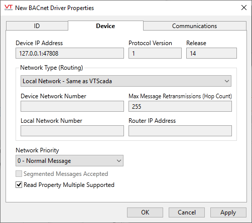
Device Address
The content and label of this field depends on the type of connection being used:
Use BACnet router disabled: the field is read-only, displaying the IP address and UDP/IP port number of the device, reflecting the configuration of the selected UDP/IP port tag.
Use BACnet router enabled: the field is user-editable, to enter the MAC Address of the routed device. The MAC Address is network-specific, according to the Device Network Type drop-list:
| Device Network Type | Parameter name | Notes |
|---|---|---|
| BACnet/IP | Device IP Address | Editable |
| MS/TP | Device Node | Editable. Accepts values between 0 and 254 |
| ISO 8802-3 (Ethernet) | Device Ethernet MAC Address | Editable |
| ARCNET | Device ARCNET ID | Editable |
| Point-To-Point | No device address | Not editable |
| LonTalk | Device MAC Address (Hexadecimal) | Editable |
| ZigBee | Device VMAC Address | Editable |
Protocol Version and Release
Displays the ASHRAE standard protocol version that the driver follows, which is version 1.14. This value is not user-configurable.
Use a BACnet router
Select this option if the device is not physically connected to the station where VTScada is installed, but can be reached through a BACnet router. When enabled, the selected UDP/IP port tag is used to connect to the BACnet router, instead of the device itself.
Device Network Type
Enabled only when using a BACnet router. Affects the contents of the Device Address field. Used to inform the driver the type of the network the routed device is connected to as follows:
-
BACnet/IP: the device is connected to an IP network that cannot be directly accessed by the station where VTScada is installed. Device Address is used to set the IP address and UDP port number of the device. If no port is specified, the default BACnet port (47808) is used.
-
MS/TP: the device is connected to a serial Master-Slave/Token Passing network, using a EIA-485 physical layer. Device Address sets the number of the device (node) in the multi-drop serial network, between 0 and 254.
-
ISO 8802-3 (Ethernet): the device is connected to a ISO 8802-3 (“Ethernet”) LAN that does not use the IP Protocol. Device address sets the Ethernet Media Access Control (MAC) address, in the standard hexadecimal format (XX-XX-XX-XX-XX-XX).
-
ARCNET: the device is connected to a ARCNET LAN, as described in ATA 878.1. Device Address sets the ARCNET ID of the device, between 1 and 255.
-
Point-To-Point: the device is connected to a serial Point-To-Point network, through a BACnet Half-Router supporting a EIA-232 connection. Device Address is unavailable, as the destination network shall contain only a single device in this configuration.
-
LonTalk: the device is connected to a EIA/CEA-709.1 (“LonTalk”) LAN. Device Address sets the MAC Address of the device, encoded as either two hexadecimal bytes, representing a combination of the DstSubnet, DstGroup and DstNode of the device, or seven hexadecimal bytes, representing the Neuron_ID of the device. Check the BACnet Standard, clauses 6.2.2.2 and 11 for more details.
-
ZigBee: the device is connected to a wireless “ZigBee” network. Device Address sets the VMAC Address configured in the table used by the network where the device is located, encoded as an integer between 0 and 4194303. Check the BACnet Standard, annexes H.7 and O for more details.
Router IP Address
Enabled only when using a BACnet router. Displays the IP address and UDP/IP port number of the router, reflecting the configuration of the selected UDP/IP port tag.
Device Network Number
Enabled only when using a BACnet router. The network number where the VTScada Station is located. Accepts network numbers between 1 and 65534.
BACnet Driver properties Communications tab
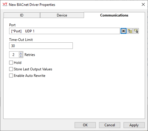
Port
The UDP/IP port tag with the IP address and port of the device or router used to reach the device.
Note that the default UDP port used for BACnet/IP is 47808, but all BACnet devices must support, at a minimum, values in the ranges 47808 - 47823 and 49152 - 65535.
Multiple drivers using the same router to reach their peer devices must use a single shared port tag.
Response Timeout (s)
Maximum time (in seconds) that the driver will wait to receive a response to a request after the last segment of the message is transmitted, before attempting a retry. This parameter is used to set the parameter Tout, as described in the BACnet Standard, clause 5.4.
Segment Timeout
Maximum time (in seconds) that the driver will wait after sending a SegmentACK to receive an additional segment of the incoming message, or for a SegmentACK after sending the final segment of a sequence, before attempting a retry. This parameter is used to set the parameters Tseg and Twait_for_seg, as described in the BACnet Standard, clause 5.4.
Retries
The number of times to retry a message before declaring an error.
Hold
Select this to have I/O tags attached to the driver hold their last value in the event of a communication failure. If not selected, tags will have their value set to invalid on a communication failure.
Store Last Output Values
When selected, the driver will maintain a record of the last value written to each output address. This may be useful in at least two situations:
- For hardware that does not maintain its state during a power loss and must be restored to that state when re-started.
- When failed hardware is replaced by a new device and you would like to start that device with the values last written to the old one.
If the last output values are stored, they may be re-written by either of two methods:
- Automatically, when communication is restored to the device.
- Manually by way of a button press. See, Rewrite Outputs Widget for details.
Changing this value from selected to deselected will cause all stored values to be erased immediately.
If this driver is being used in conjunction with a Driver Multiplexer, then configure the Driver Multiplexer to store the last values, not the drivers connected to the Multiplexer. In this case, only the Multiplexer should be configured to re-write automatically.
Enable Auto Rewrite
If selected, the Store Last Output Values option will also be activated. This option causes the driver to rewrite the last value written to each output, in the event that communications are lost and then restored.
Use this option only if you are certain that you want the last values to be rewritten automatically after an interruption in driver communications.
BACnet Driver properties - Advanced tab
The parameters in this tab are usually best left at their defaults.
Used to troubleshoot connection issues, especially when limited routed networks, or older, less capable devices, are involved. Changing any of these parameters may negatively affect the performance and reliability of the driver. Advanced knowledge of the BACnet Protocol is recommended before attempting any changes.
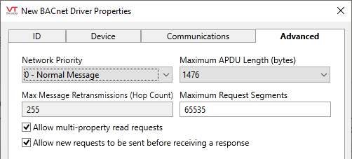
Network Priority
The message priority to determine how messages to the device will be prioritized by routers along the path (not to be confused with property write priorities). Does not affect local connections. May be set to any of:
- 0 – Normal Message
- 1 – Urgent Message
- 2 – Critical Equipment Message
- 3 – Life Safety Message
Maximum APDU Length
The maximum number of bytes that a BACnet Application Protocol Data Unit can have before the message is divided in segments. This parameter is used to limit the size of packets going through multiple routed networks with unpredictable capacity. The actual APDU length will be the smaller between the standard for the network type chosen in the Device tab (1476 if not routed), the value chosen in this list, and the value reported by the device. Valid options are (in bytes):
- 50
- 128
- 206 (fits in a LonTalk frame)
- 480 (fits in a MS/TP, ARCNET, Point-To-Point or ZigBee frame)
- 1024
- 1476 (fits in an ISO 8802-3 or BACnet/IP frame)
Max Message Retransmissions (Hop Count)
The maximum times a message is retransmitted by routers when attempting to reach another network. This number is decremented every time a router receives a message and attempts to forward it to the next destination in the BACnet internetwork. It is intended to prevent messages from using network resources indefinitely when the ultimate destination is unreachable. Accepts values between 1 and 255.
Maximum Request Segments
Sets the maximum segments that a request message from the driver may have. For performance reasons, the driver will typically attempt to compose request messages that fit in a single segment and result in a single segment as response, but some data types, such as strings, may result in messages with hard to predict sizes. Some older devices may not support segmentation or may support too few segments for a response message, and it might not be possible to retrieve the information about device capabilities. If this field is set to the minimum of one segment, the driver will use a single request for each address resulting in responses containing strings.
Allow multi-property read requests
Disabling this option further limits the number of addresses that can be requested in a single message to one. It might be required when a device does not support ReadPropertyMultiple Service requests, and the driver is unable to retrieve the information about device capabilities.
Allow new requests to be sent before receiving a response
The BACnet Driver supports sending and receiving up to 256 simultaneous messages to and from a single device. Some devices with lower hardware capabilities, though, may not be able to reply to multiple messages in a timely manner, resulting in messages being discarded due to timeouts. By disabling this option, the driver will wait for either a response from the device or a timeout, before sending the next request in the queue.
The following widgets are available to display information about your BACnet driver tags:
