Write I/O (Tutorial)
The following exercise assumes that you have completed all the tutorial lessons prior to this in the menu. If so, ignore this note and continue.
If not, you can still do this exercise. Load the Training Simulator, as described in Add Applications (Tutorial). Navigate to the Sample Pages >> Demo Page and follow the instructions there to enable the Demo System tags. You will need to make adjustments in the exercise steps since the path to the tags won't be the same, and the Demo System has been built to a state that may not match that of the previous chapter in this tutorial.
The simulated system that you're building will be more interesting if you have a way to control it. In this section you'll see how to open and close the valve that allows fluid to flow into the tank. You'll also see how to adjust the speed of the pump that drains it.
Preparation: Monitor flow into and out of the tank.
- Open the Tag Browser.
- Navigate into Station 1 to select CommChannel.
- Right-click on CommChannel to open the pop-up menu.
- Select New Child.
The Select Type dialog opens. - Select I/O and Calculations.
- Name the tag, Inflow
- Set the description to Flow into storage
- Ensure that the data type is set to Analog.
- Select the I/O tab.
- Ensure that the I/O Device is set to [*Driver] Simulator connection
- Set the read address to 40003/float.
Why "/float"? Just for the sake of seeing & using an alternative addressing format. Look in the reference section of the documentation for a list of data suffixes for tag I/O addressing. - Set the scan interval to 2.
In general, scan as often as needed, but not any more often than needed. - Select the Scaling tab.
- Set the Unscaled Process Data values to 0 and 200 for Min and Max.
- Set the Scaled Process Data values to 0 and 200 for Min and Max.
The Display Range and Expected Range values are blank. - Select the Display tab.
- Set the Engineering Units to gpm.
- Set Digits After Decimal to 1.
- Set the color to a shade of blue other than set for the Level tag.
- Click OK to save your work and close the properties dialog.
- Draw this tag as a Numeric Value on the Station Status page.
(Step-by-step instructions not provided. You've seen enough by now to do this on your own. Refer to the documentation if you need help.) - Use the text tool in the Home ribbon to add a text label above the Numeric Value: Flow into storage.
In the simulator's code, the inflow rate is set to change randomly every few minutes.
Where Inflow belonged to the station in general, outflow is a direct result of what the pump is doing, so you'll put the next tag into that context.
- Close the Idea Studio and open the Tag Browser.
- Find and right-click on Pump 1 to open the pop-up menu.
- Select New Child.
The Select Type dialog opens. - Select I/O and Calculations.
- Name the tag, Flow
Since this is a child of Pump 1, there should be no need to explain "flow of what" in the name. - Set the description to Flow rate
Notice that the description from the last tag was still there? This can save you time when creating several similar tags. - Ensure that the data type is set to Analog.
- Select the I/O tab.
- Ensure that the I/O Device reads, [*Driver] Simulator connection
- Set the read address to 40033.
- Set the scan interval to 2.
- Select the Scaling tab.
- Set the Unscaled Process Data values to 0 and 200 for Min and Max.
- Set the Scaled Process Data values to 0 and 200 for Min and Max.
- Select the Display tab.
- Set the Engineering Units to gpm.
- Click OK to save your work and close the properties dialog.
- Draw this tag as a Numeric Value placing it near the pump Equipment widget.
If Running is 0, that's also what the Flow rate will be. As soon as the pump re-starts you'll see a flow.
Create a digital control
The control for the inlet valve is simple. It can be open or closed. There is no control over how much it is open.
The controller has two input coil addresses for the valve: 00002 monitors the current state (feedback for the open or closed state) and 00001 is used for control. Both will be used in this tag.
- Open the Tag Browser if it is not already open.
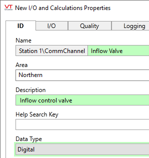
- As a child of CommChannel, create a new I/O and Calculations tag.
- Name the tag, Inflow Valve.
- Set the description to Inflow control valve
- Change the data type to Digital.
- Select the I/O tab.
- Set the Read Address to 2
- Set the Write Address to 1
- Click OK to save your work and close the dialog.
Do not close the Tag Browser
That's all there was to creating the I/O. But, you still need a widget so that you can tell it what to write, and when.
Care is required when configuring both a read and a write address. Only values from the read address are shown as the value of the tag. If the value at the read address differs from the value written, the tag's Mismatch variable is set to TRUE, as reflected in widgets linked to this tag. The value at the read address is NOT sent to the write address on change.
In this example, the read address is providing independent feedback of the value written to the write address.
Draw a digital control widget
You will draw this control as a pair of Set Value Button Widgets. One button will write a 1 to open the valve and the other will write a 0 to close it.
- While continuing to work in the Tag Browser, right-click on the tag you just created, Inflow Valve.
- In the pop-up menu, select Draw.
The Idea Studio opens, and in front of it a separate window for the widgets palette. - In the floating widgets palette, open the Buttons & Switches folder.
- Open the Basic Controls folder.
(You may need to scroll down to see it.) - Select the Set Value Button and drag it to the Idea Studio page, placing it near the number that shows the inflow rate.
(Careful! Be sure that you've selected the Set Value Button, not the Momentary Button.) - When the Tag Browser reopens, close it.
- Now working in the Idea Studio, right-click on your Set Value button.
A pop-up menu opens. - Select Properties from that menu.
The Set Value Button Properties dialog opens. - In the space for the State 0 Label, type Open
- In the space for the State 1 Label, type Opened
- Select the option, Write 1 Immediately
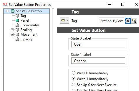
- Select OK to save your work and close the dialog.
To create the Close control, you'll copy and paste the last button rather than create a new one.
- Ensure that the "Open" button is selected in the Idea Studio.
- Press the keyboard combination Ctrl + C to copy it.
- Press the keyboard combination Ctrl + V to paste.
The copy will appear in the center of the page. - Drag the new copy to a position below the original button.
- Right-click on the copy and select "Properties" from the dialog that opens.
- Change the two labels to Closed and Close, in that order.
- Select the option, Write 0 Immediately.
- Close the Idea Studio and operate the valve.
You should see the inflow rate drop to zero when the valve is closed. Give the simulator time to process each operation. Note that if the inflow valve stays closed for very long, not much else is going to happen in this system. You'll want to leave it open most of the time.
Create an analog control
The pump has a slightly better control system than the valve. It's top running speed is 1200 rpm and it can be set to any value between that and zero. The controller uses holding register 40037 for the speed setpoint. It also uses holding register 40039 for independent confirmation of that setpoint. Not every system will be programmed this way, but it's nice when available. And you still need only one tag.
- Open the Tag Browser.
- Right-click on Pump 1 and select New Child from the menu that opens.
- Select I/O and Calculations as the type.
- Name the tag, Speed Set.
- Describe it as Motor speed setpoint
- Set the data type to Analog.
- Select the I/O tab.
- Set the Read Address to 40039
- Set the Write Address to 40037
- Select the Scaling tab.
- Set both the Max Unscaled Process Data and the Max Scaled Process data to 1200
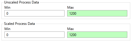
(Inputs use scaling only to map raw values to engineering units. The value is not limited to these settings.
Outputs use the Scaled Process Data settings as limits.) - Open the Display tab.
- Set the Engineering Units to rpm
- Select OK to save your work and close the properties dialog.
A moment or two after saving, the system should read the feedback address (40039) and the tag's value will show as 640, the default for the simulation.
Draw an analog control widget
There are several widgets that you could use for operator control of this tag; Rotary Control Widget (Knob), Slider Widget, Set Analog Value Widget, and more. The next exercise uses a rotary control, but you can choose any of the others if you prefer.
- Continuing to work in the Tag Browser, right-click on the tag you just created, Speed Set.
- In the menu that opens, select Draw.
- In the widgets palette, navigate to the Analog Controls folder.
- Drag a Silver Knob to the open page in the Idea Studio, placing it below or near the pump.
- When the Tag Browser reopens, close it.
The Multi Image Widgets panel opened on the right of the Idea Studio. Close it. - Close the Idea Studio.
You could adjust the display properties of this widget, but there's no need.
Operate the controls. When the pump is on, you should be able to change the flow rate by turning the knob. If the pump is off, the flow rate is going to be zero, no matter what the speed setpoint is.
Feeling impatient while waiting for the tank to fill and the pump turn on? If you work in the Training Simulator application and navigate to the Sample Pages folder, then Demo Pumping System page, you'll see a speed factor. The default is 25. The bigger the number, the faster the simulator will run. (maximum: 75) A lower number gives a more realistic-looking simulation.
Bonus Step: Practice what you've learned
The pump includes the following analog I/O. Create tags and draw them as widgets of your choice. In both cases, the scale value is the maximum for both the unscaled process data and the scaled process data.
| Tag Name | Description | Read Address | Scale | Eng. Units |
|---|---|---|---|---|
| Current | Electric current drawn | 40031 | 50 | Amps |
| Speed | Motor Speed | 40035 | 200 | gpm |
Ready to continue? Open Selector Switches (Tutorial)
