Digital I/O Tags (Tutorial)
To review, there are three links in the communication chain: VTScada needs a port tag to tell it where to find the equipment, a driver tag to tell it what protocol to speak, and I/O tags to tell it which registers to use on the equipment. This modular approach makes your tag structures more flexible.
I/O tags are for monitoring and controlling equipment. Therefore, it makes sense to create them below Context tags that identify what that equipment is. There is also a significant advantage to creating I/O tags below the driver they use to communicate with the remote devices. In this tutorial, you will use both of those organizational techniques.
A question that is often asked during training courses is "How do I know what address to use for an I/O tag?". That's not something that we can tell you. Whoever wrote the code for your hardware (PLC or RTU) must tell you what the address registers are. Depending on which device driver you are using, there may be an address assist button beside the I/O address field in each tag you create. For example, you'll find one if the driver is DNP3. If you're using the CIP driver, you may be able to tell VTScada to import all the tags and addresses for you
In the training simulator application, there are addresses to monitor a storage tank, addresses to monitor and control flow into that tank, and more to monitor and control a pump that will empty the tank. There are addresses for two tanks, each of which may have two pumps, but we suggest that you create only one of each at this stage. There are shortcuts for creating the others, as will be seen in later exercises.
The following exercise assumes that you have completed all the tutorial lessons prior to this in the menu. If so, ignore this note and continue.
If not, you can still do this exercise. Load the Training Simulator, as described in Add Applications (Tutorial). Navigate to the Sample Pages >> Demo Page and follow the instructions there to enable the Demo System tags. You will need to make adjustments in the exercise steps since the path to the tags won't be the same, and the Demo System has been built to a state that may not match that of the previous chapter in this tutorial.
Create Digital I/O for a pump
The first set of steps is to create a Context for the equipment. Given that the simulator has I/O for two pumps within each station, it makes sense to keep the I/O for each in its own Context.
- Open the Tag Browser.
- Right-click on CommChannel and select New Child from the menu that opens.
(You might need to navigate down through Station 1 to find CommChannel.) - Expand the Containers group and select Context.
- Name the new tag, Pump 1 (*see note at end of instructions.)
- Set the description to: Primary pump
- Select OK to save the new Context tag.
Now for the I/O. Let's start by monitoring whether the pump is running. The simulator starts in automatic mode so the pump will start and stop on an irregular cycle:
- Right-click on the Pump 1 Context tag and select New Child from the menu that opens.
- Expand the Digitals group and select I/O and Calculations (Digitals) from there.
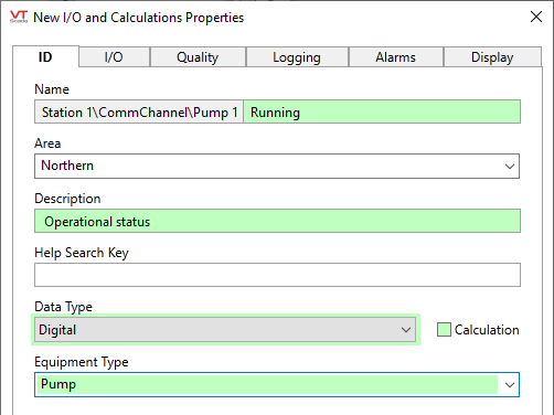
- Set the name to Running
There's no need for the name to say what is running. That's implied by the parent context. - Set the description to Operational status
- Make sure that the data type is set to Digital.
- In the Equipment Type drop-down, select Pump.
(Only this one tag should use that equipment type. In the coming exercises, make sure that the equipment type is blank.)
Configured ID tab
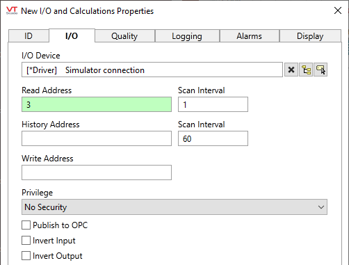
- Open the I/O tab.
- Look at the I/O Device field. It's been configured for you automatically, using the first ancestor that's a driver, [*Driver]. This is one of the benefits of creating your tags in parent-child structures.
- Set the Read address to 3
- All other values will remain the same.
Configured Digital Status I/O
- Click OK to close the properties dialog and return to the Tag Browser.
If you're curious about the other configuration fields in that tag, you can read about them in I/O and Calculations Tag.
It might take a moment for the value to appear. After it does, it will start at "stopped". Every so often it will switch to "running" while the automated system runs.
Some readers may be familiar with the Digital Status and even the much older Digital Input tag types. These still work and are still available, but you are advised to use I/O tags as much as possible in order to take advantage of features that come with these newer tags.
(*) Descriptive words are used for tag names in this tutorial, but it's not a bad idea to adopt a naming standard such as such as ISA-5.1 ("TIC-103"). Read more about that here: Best Practices for Tags
Ready to continue? Open Analog I/O Tags (Tutorial)
