Analog I/O Tags (Tutorial)
Use digital I/O tags for anything that is either on or off, like a light switch. Use analogs to represent a range of values such as a level, pressure, voltage, or brightness.
Like digitals, analogs link to drivers and have an address field that matches a register on the PLC. They also have scaling values, translating the raw machine values into numbers that mean something to humans. These are the engineering units of the tag. For example, the equipment might have a range of values from zero to 5 Volts, measured in tenths of a volt. That gives you an unscaled minimum of zero and an unscaled maximum of 50. But perhaps you want to express that as a percentage of the possible range. You would configure the tag's scaled minimum to zero, but the scaled maximum to 100. VTScada will translate the raw values into scaled values for you so that 2.5V looks like 50%.
Monitor an analog value
The following exercise assumes that you have completed all the tutorial lessons prior to this in the menu. If so, ignore this note and continue.
If not, you can still do this exercise. Load the Training Simulator, as described in Add Applications (Tutorial). Navigate to the Sample Pages >> Demo Page and follow the instructions there to enable the Demo System tags. You will need to make adjustments in the exercise steps since the path to the tags won't be the same, and the Demo System has been built to a state that may not match that of the previous chapter in this tutorial.
Let's create an analog I/O tag to monitor the level in the tank. You'll be able to watch it to get a sense of the setpoints that signal the pump to start and stop.
- Open the Tag Browser.
- Navigate to Station 1 >> CommChannel.
- Add a new child tag below CommChannel, selecting I/O and Calculation as the type.
(Yes, exactly the same type of tag you created for a digital. Keep going.) - Name the tag, Level
- Describe it as Holding tank level
- Ensure that the data type is set to Analog.
- Ensure that the equipment type is blank.
- Open the I/O tab.
- Ensure that the I/O device is [*Driver] Simulator Connection.
- Set the Read Address to 40001
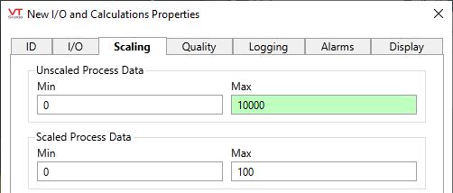
(The History Address and Write Address are left blank.) - Open the Scaling tab.
Notice the that the default values for the two process data scales (unscaled and scaled) are from 0 to 100.
For the Modbus, all values are integers. (Unless your system uses the /float option, which this register doesn't.)
But, it can make an integer look like a floating point if, for example, the unscaled values range from 0 to 10000, but the scaled values are only 0 to 100. That gives us two decimal points in the display. By coincidence, that's how this register was configured.
- Change the Unscaled Process Data - Max value to 10000
- Leave the other values at their defaults. Display and Expected ranges have to do with presentation rather than collection of data.
- Open the Logging tab.
- Set the deadband amount to 0.03
Thanks to the scaling, this tag will record changes of 1/100 in value. But, perhaps there's system noise of +/- 0.02. There's no point to recording that, so you might set the deadband to 0.03. This says that the value must change by at least 0.03 before the tag will log the new value.
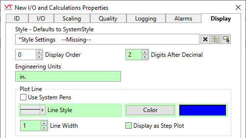
Setting a deadband on the amount to log is an usually a good idea, since there is always system noise. Just don't set it so high that you miss important information. - Open the Display tab.
- Our tag has been scaled to show hundredths, so set the number of digits after the decimal point to 2
- The depth of the holding tank is measured in inches, so set the engineering units to in.
- In preparation for the trending lesson of this tutorial, set the color to a shade of blue.
- Select the OK button.
Note that the Tag Browser will show only one digit after the decimal, however you configured your tags.
In a later tutorial installment, you will have the opportunity to configure an alarm on this tag.
Ready to continue? Open Idea Studio (Tutorial)
