Alarms (Tutorial)
The following exercise assumes that you have completed all the tutorial lessons prior to this in the menu. If so, ignore this note and continue.
If not, you can still do this exercise. Load the Training Simulator, as described in Add Applications (Tutorial). Navigate to the Sample Pages >> Demo Page and follow the instructions there to enable the Demo System tags. You will need to make adjustments in the exercise steps since the path to the tags won't be the same, and the Demo System has been built to a state that may not match that of the previous chapter in this tutorial.
Alarms can be loud. Before starting this tutorial session, ensure that you can find the volume control for any speakers attached to your computer.
It is worth your time to review the ISA 18.2 standard, which relates to alarms and alarm management. VTScada provides all the tools that you need to be ISA 18.2 compliant.
I/O tags (and many others) have alarm configuration built-in. For tags that do not, you can create independent Alarm tags, triggered by whatever condition means an alarm. Before working with the Alarm page, you'll need a couple of alarms to see, so that's where this installment begins.
Add an alarm to an analog I/O tag
- Open the Tag Browser.
- Navigate to the tag, "Level", below CommChannel.
- Open the properties dialog of Level.
- Open the Alarms tab.
Basic configuration of four built-in alarms is shown. - Set the High Alarm Priority to [2] High.
An alarm must have a priority before anything else can be configured. - In the High Alarm Setpoint field, replace the 90 with 80.
- Do not set a High Alarm Delay.
A delay helps avoid nuisance alarms that are transient in nature.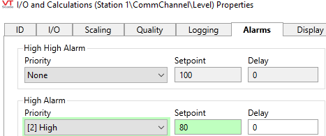
- Leave the properties dialog open while you read the following.
For many alarms, the preceding steps are all you would need. But, there are certainly more options available if required.
- Continuing to work in the Alarms tab, select the Advanced option.
The tab changes. You are now working with one alarm at a time - Change the alarm selection from High High Alarm to High Alarm.
The work you did earlier is now visible. - Note the Deadband option.
If the value triggering the alarm keeps dipping below the setpoint (like a ripple on a pond) it can be an annoyance. The deadband doesn't change the setpoint. It changes the point at which we say that the condition that caused the alarm has returned to a normal state.
Do not set a deadband for this exercise. - Do not set an Alarm Rearm Time.
Rearming causes alarm notifications to restart if an operator acknowledges the alarm but then does nothing to bring the level below the trigger setpoint within a period of time. - Do not select the Disable option.
Disabling an alarm is a configuration option, not an operational action. (Operators can shelve alarms.)
If you need to tie this to a switch or a state of the application, use separate Alarm tags rather than the built-in alarms. - Note that you cannot select the Popup option.
Alarm pop-ups must be enabled in the Application Configuration dialog before they can be applied to individual alarms. A pop-up forces the operator to acknowledge the alarm immediately. - Do not provide a sound file.
Some sites use .WAV files for alarm sounds. - Click OK to save your work and close the dialog.
Turn off the pump and wait for the tank to fill until it reaches the setpoint. Be ready to turn down the volume level of your computer's speakers.
Add an alarm to a digital I/O tag
The pump is configured to fault if it continues to operate after the tank is empty. When this happens, a fault status bit will be set in the (simulated) PLC.
- Open the Tag Browser.
- Navigate to Pump 1 and right-click to open its pop-up menu.
- Select, New Child from that menu.
- Select I/O and Calculations as the type.
- Name the tag Fault.
- Set the Description to Motor burnout fault.
- Set the data type to Digital.
- Select the I/O tab.
- Ensure that the I/O Device is configured as [*Driver] Simulator connection
- Set the Read Address to 7
- Ensure that there is no value for the Write Address or History Address.
- Select the Alarms tab.
Note that only one type is available: State alarm. - Set the Priority to [1] Critical
- Ensure that the State is set to 1
- Select the Trip option.
See following discussion. - Select OK to save your work and close the properties dialog.
- Close the Tag Browser.
- Set the pump to Hand mode (ON) and wait for the tank to drain.
The alarm will trip several seconds after the level reaches zero. The motor will switch off (since it burned out) while the switch remains in the Hand position. To reset the motor, switch to OFF, then to any other state. This will clear the fault condition, but that has no relation to the fact that the alarm has tripped and remains tripped.
Trip alarms versus active alarms
The term "active" can be confusing. The thing to remember is that it refers to the cause of the alarm, not to the alarm itself, even though you are likely to hear people use the term "active alarm". By that, they mean an alarm whose cause has not returned to a normal operating condition.
There may be situations where the state of the system is not relevant after the alarm starts. All that you care about is that something rang the alarm. This is when you would configure the alarm as a trip alarm. A trip alarm is just as much an alarm as any other, but it will never be included in the list of "active alarms". A classic example is a burglar alarm where the alarm is triggered when the door opens. Nobody cares whether the burglar had the good manners to close the door after entering. The burglar alarm is not in the "active" list but it is still very "current" and there are lots of flashing lights and sirens.
Trip alarms are triggered only by digital I/O (or the equivalent). But there is no requirement that every alarm triggered by a digital value must be configured as a trip alarm.
Respond to alarms
After creating and triggering alarms, you can open the Alarm page to view the alarm lists. A full description of the page and various alarm features can be found here: Alarm Display & Tasks. You are encouraged to explore the options before acknowledging your alarms. Or, acknowledge current alarms and then operate the system to generate new alarms. Note that there are several reporting tools that you can use for Alarm Analysis. You can also Customize Alarm Management so that operators can view and respond to alarms on the same page where they view and manage related equipment.
